When considered simplistically, diagram 14 gives an indication to how a sample is analysed in a neutron scattering device (such as LOQ at ISIS).
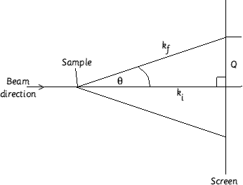
Diagram 14. A simplistic representation of a neutron scattering experiment.
The focused beam (generated by a cyclotron or syncrotron) is shone at the sample. Depending on the sample and it's nuclear spin properties (a neutron having a spin ½ and magnetic moment of μn=-1.913 μN) will depend on how the beam is defracted on the screen. Q (19) is the distance between the line of the beam and the scattered particle. The intensity of the detected beam will depend on the number of neutrons released from the nucleus.
19
The cyclotron is a device which generates neutrons (typically by fission in nuclear reactions with typical energies of 106 eV or by pulsed sources) at or near thermal energies.
A pulsed source has advantages over a nuclear reactor source in that it generates less heat per neutron (High Flux Beam Reactors yield around 1015 n cm-2 s-1 due to the heat transfer limitations) and secondly, the neutron "brightness" can be concentrated into a fraction of the total time and then use time-of-flight calculations to determine the neutron energy.
A pulsed source also has the advantage of only requiring a single source to produce neutrons across a wide range energies. The high end (hot) neutrons are made available by slowing down the spectrum.
The neutron energy is often measured by time-of-flight and is expressing in terms of μ sec m-1.
20
(25.3 meV º 454 μ sec m-1)
The use of neutrons in scattering is reliant on four factors :
- They have energies comparable to the vibration frequencies of the nuclei of the atoms in the solid
- The wavelengths are comparable to those of the atomic separations
- There is a weak nuclear interaction giving good penetration
- There is a comparable interaction with unpaired electrons
All of these measurements are made simultaneously with measurements of energy transfer and diffraction. The diffraction from the magnetic structures of materials provide a way of investigating the microscopic magnetic structure.
In practise, a beam of radiation (which does not have to be monochromatic) is directed at a sample. The beam is collimated to a small beam. This illuminates a small volume, V (= cross sectional area of the beam x path length of the sample). Some of the radiation will be absorbed (with the rest reflected or scattered). Behind the sample is a detector positioned at a distance Lsd, and the scattering angle, q, records the flux of the radiation scattered into a solid element, ΔΩ (= dimensions of the detector / L2sd). The flux, I (l,q) can now be expressed in general terms as
21
where I0 is the incident flux, h the detector efficient, T = sample transmission and δρ/δ&Omega (Q) the differential cross section. δ&rho/δΩ can be derived from the observed counts.
Small angle neutron scattering (SANS) for small Qs correspond to lengths greater than atomic separation therefore giving fluctuation in average scattering densities.
A SANS experiment has the objective to find the differential of cross section as this gives information on shape, size and elastic interactions with other scattering entities in the sample. The differential cross section is given by
21
where Np is the number concentration of scattering bodies (p = particles), Vp is the volume of one scattering body, (δ&Delta)2 is the square of the difference in the neutron scattering length density (otherwise known as the contrast), P(Q) is function known as the shape factor, S(Q) is the interparticle factor, Q is the modulus of the scattering vector and Binc is the (isotropic) incoherent background signal.
The differential cross section has dimensions of length-1 (most commonly, cm-1). This is the macroscopic cross section, usually Σs
The differential cross section is normally written as the simple form I( γ,Q).
Definitions
Q, the scattering vector is the modulus of the vector difference, the incident and the scattered wave vectors (23). kf and ki are shown in diagram 14.
23
with n (neutron effective refractive index) » 1.
Substituting (23) into Bragg's law of diffraction (24a), (24b) is obtained with d = a distance. This is a dimension in real space that constrains scattering around Q in reciprocal space.
24a
24b
The significance of this simple derivation is that it now becomes fast to "size" the scattering bodies in the sample from the shape of S(Q). At ISIS, Q has a range of 0.06 - 10 nm-1, which allows a probing range from 0.6 - 100 nm.
The contrast.
The neutron scattering length density, δ, of a molecule containing i atoms can be readily calculated using (25)
25
where D is the bulk density of the scattering body and Mw the molecular weight. The contrast is the difference in δ values between the part of the sample of interest, δp, and the rest of the matrix, δm. This value is squared (26). If (Dδ)2 is zero, then there can be no scattering. When this point is reached, the scattering bodies are said to be at contrast match - this makes the interpretation of the scattering patterns a great deal simpler as the bulk liquid (say) is matched out and only the chemisorbed liquid on the surface of the particle is observed.
26
The form factor.
This describes how I(Q) is modulated by interference effects between radiation scattered by different parts of the same body. It is therefore very dependant on the shape of the scattering body. The general form of P(Q) is given by Van de Hulst's equation (27).
27
where α is the "shape parameter" (this may represent a length or radius of gyration). A number of analytic expressions exist for the most common shapes and from these, more complex expressions can be derived. Two of these are the Guinier [5] and Porod approximations [6].
In the case of the scattering from an opal crystal, the scattering will have a lattice scattering vectors R [7]. In the Guinier approximation (valid for Δkr << 1 - close to the forward direction), R denotes the dimension of the inhomogenity. The approximation can be described by (28a) where Rg is the Guinier radius.
28a
The Porod approximation states the functional relation of the scattering law in the asymptotic regime QR >>1 for an inhomogenity with constant electron density and a sharp boundary (28b).
28b
The structure factor
This is given by (29)
29
g(r) is the sine Fourier transform of S(Q). For a periodic lattice,
S(Q) equals a constant
![]() .
.
(29) is a function which describes how I(Q) is modulated by interference effects between radiation scattered by different scattering bodies. It follows that it is dependant on how ordered the sample is. Small angle scattering can be used to gain information about the relative positions of the scattering bodies through the radial distribution function (30)
30
where r is the radial distance outward from the centre of the scattering body. g(r) is obtained from (29). G(r) is normally a damped, oscillating density distribution function with the maxima corresponding to the the distance to the nearest neighbour. Moreover, ln g(r) is directly related to the potential energy function which describes the interaction between the scattering bodies. If g(r) equals zero, S(Q) equals one and the scattering is just then the form factor.